Raphael Fortuna ECE 3400 Wiki
Project maintained by raf269 Hosted on GitHub Pages — Theme by mattgraham
Lab 1
Home
Lab 2
Lab 3
Lab 4
Summary of what was accomplished during the lab
- We assembled the robot frame
- We connected our servos to the Arduino Nano Every and wired up the bread board to be able to move around
- We created a Servo Demo code file with a movement function for turning left, and right and moving forwards and calibrated our servos to move together for our robot to
- We had the robot stop for 5 seconds, robot drive north for 20 centimeters, turn to the right by 90 degrees after a second passes, turn to the left by 270 degrees after a second passes, go south for 20 centimeters after a second passes, turn to the right by 180 degrees after a second passes, and then stop for the Servo Demo
- We added and wired 3 ultrasonic sensors to the front left and right side of our robot
- We modified the given US demo file to test the ultrasonic sensors and understand how the data capture worked
- We merged our Servo demo code and US demo file to create the US demo 2 file that included a state machine, new controls to our robot, and serial output for where the robot was in the course
Assembling and wiring the robot
To assemble the robot frame, we gathered a caster wheel, two servo motors, some Velcro, batteries, breadboard, and Arduino Nano Every and assembled them into the robot. We then wired the robot.
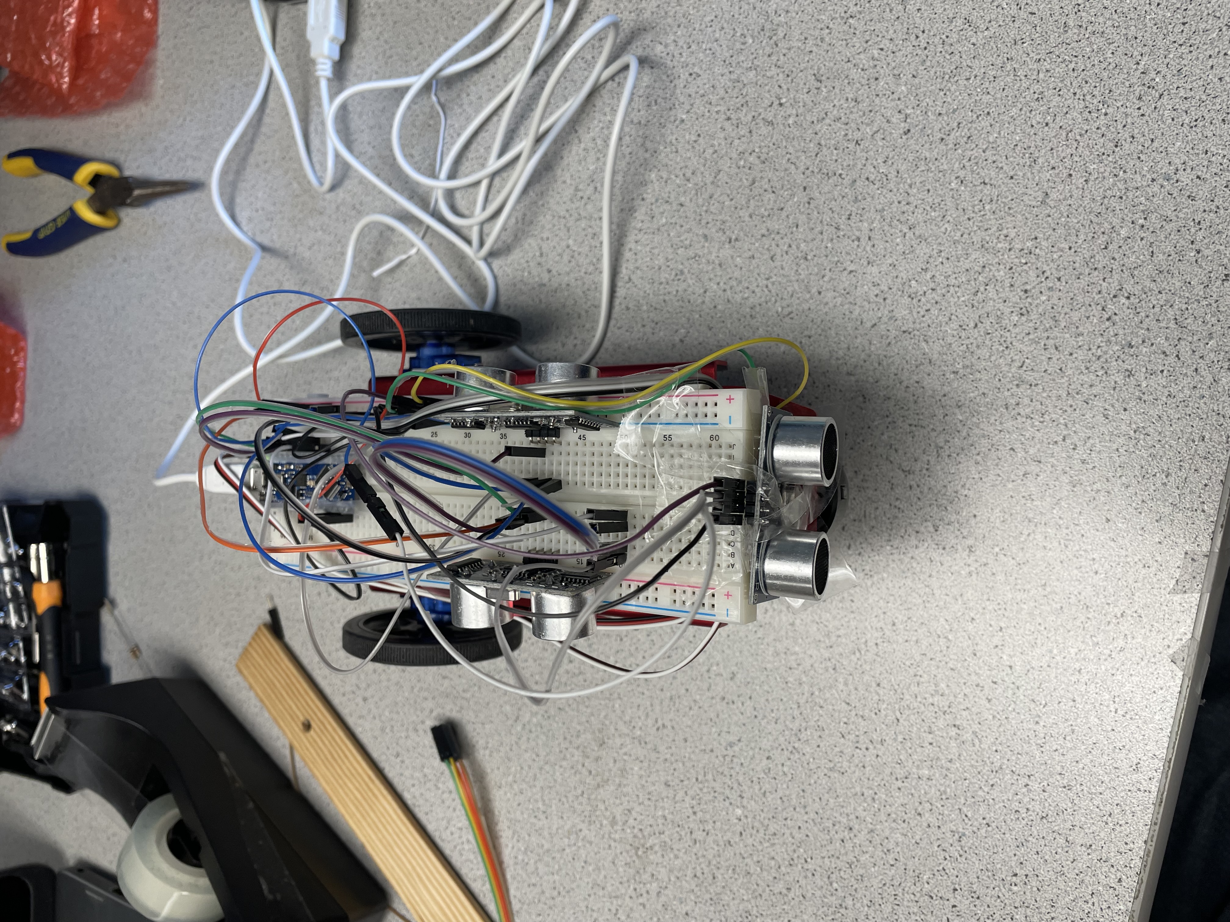
Also added here all the ultrasonic sensors that we later added during the ultrasonic sensor part.
One of the challenges we had with a robot was one of our servo motors was acting erratically so we had to swap it out midway through our lab.
Servo Demo
To have the robot drive along the first path for the first servo task, we first found the values that would make each servo drive in unison with each other.
We then repeated this process for turning left and right and used a delay to turn 90 degrees. We implemented these actions in a function with a variety of different movement commands that can be run based on the input to avoid code repetition and increase modularity, as we would add to this movement function later in the lab for the US Demo 2.
Ultrasonic Sensor Assembly, Testing, and Demo
To start, we added the ultrasonic sensors to the left and right of the circuit board and taped one to the front of the robot to be able to determine the distance on the left, right, and front. Then we wired the sensors to the Arduino Nano Every and modified the provided ultrasonic sensor code to be able to test the sensors with different distances.
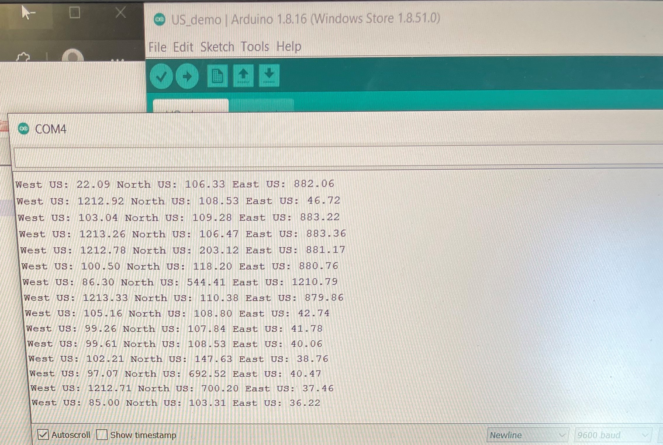
Here is a picture of when running the first ultrasonic sensor demo
US Demo 2 – Navigation
For this last part of the lab, we merged our Servo demo code and US demo together and added some extra functions to it which included turning 180 degrees to the right, 540 degrees the left, and pausing for 1 second.
We then had this decide on a way for us to traverse the course. We decided to use a state machine and created objects that represented each motion we would have to do such as turning, moving, or stopping and then create conditions that would allow for us to transition to each state after we reached a certain section of the course. These transitions were based on information collected by the ultrasonic sensors.
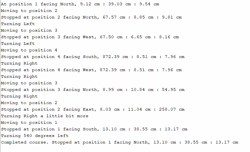
Finally, we added a serial monitor output to show what the robot was doing as it drove through the course, with a “compass” to keep track of its new direction each time it turned.
Some of the challenges we faced when trying us having our robot drive the course included making sure the robot stopped and turned where it had to since sometimes it would veer off ever so slightly or start slipping because the servo wheels or caster wheel was dirty. To solve these challenges, we use the rubber pads provided in the lab as a floor for our robot to drive on and replaced our caster wheel. To reduce the errors with turning and moving we went through and calibrated the robot’s state transitions for each part of the course.
A really interesting bug that we found during this last part was that after we completed the 540 degree turn, our robot would sometimes make a small right turn and this right turn that was roughly 90 degrees. We were unsure about why this was happening, but then saw we had a possible index out of range error that could cause the Arduino to read and use random register data and act on it if it was in the correct format at the end of our state machine. This was fixed by adding a bounds check to our state machine transition function.
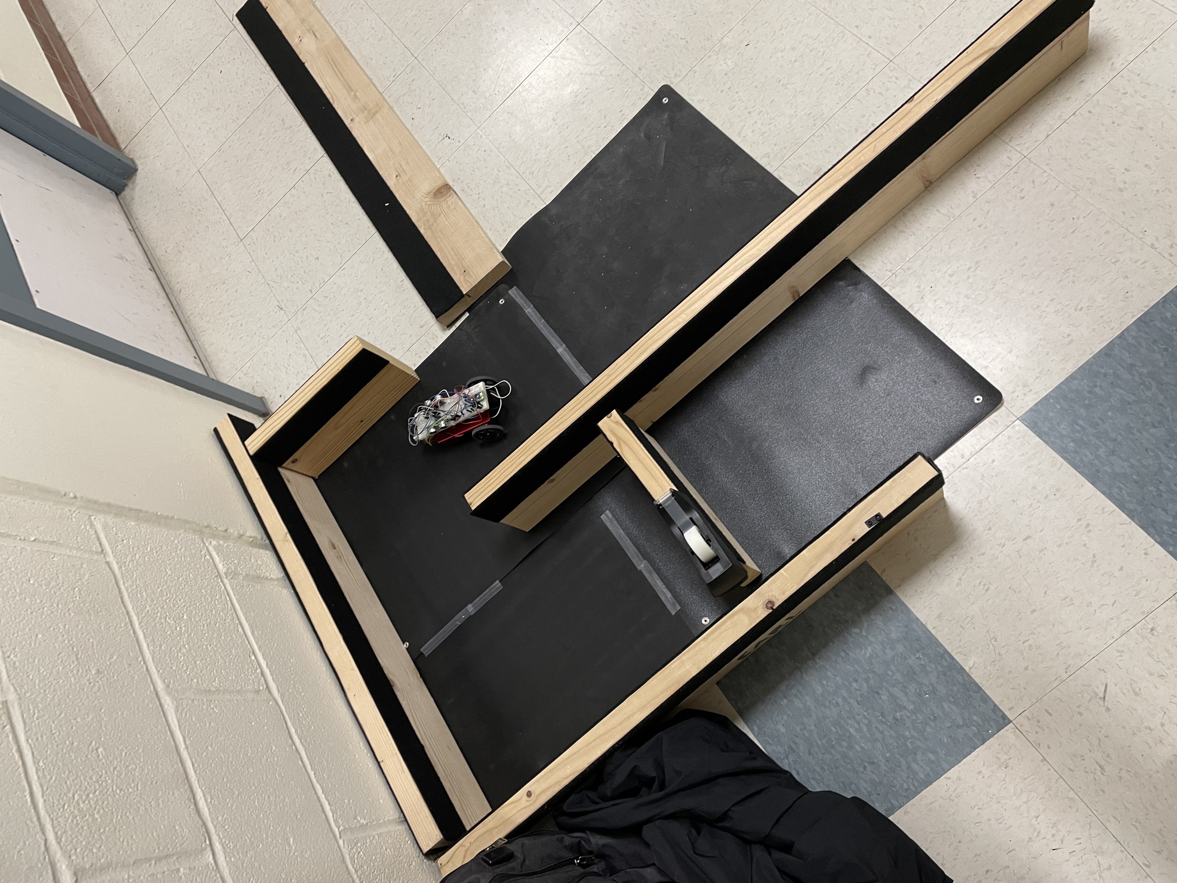
Here you can see the robot driving on the course
Here you can see a picture of the course with the robot to see how we built it
Here is a picture of our serial output an example serial output